The M-19 Story
Test Flight of the Mooney M-19
You may recall that the M-19 was a specially modified M-18C-55 which
Mooney developed as a counter-liaison aircraft they called the "Cub-Killer." It
featured a 90 h.p. engine with a Flottorp constant speed propeller and .30
caliber machine guns in the wings. No one seems to know where the M-19 is now --
even photos of the plane are as rare as hens' teeth. Only stories remain. Here
is a good one from long-time Mooney man, Bill
Wheat....
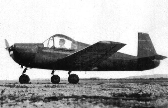 "The photo is definitely the M-19. The pilot is
Bill Taylor [Mooney's general manager]. Due to the quality of
the picture I cannot be certain as to whether it is as presented to the Military
or repainted and cleaned up as a company run-about. The original was a dull
olive-drab all over and was as ugly as all-get-out."
"The photo is definitely the M-19. The pilot is
Bill Taylor [Mooney's general manager]. Due to the quality of
the picture I cannot be certain as to whether it is as presented to the Military
or repainted and cleaned up as a company run-about. The original was a dull
olive-drab all over and was as ugly as all-get-out."
"Taylor's first flight lasted about an hour and a half. Normally, the first
flight of a proto-type was about 15 minutes. Everyone was in front of the
factory and getting worried.
When he finally taxied up and got out, someone asked him what he was going
to name it. He stood on the wing for a moment and finally answered, 'Old
Puss.'
Al Mooney asked why and Bill replied, 'It's the only thing
I can think of that looks so bad and feels so good!'"
27 October, 2000
Development history of the M-19
The following articles are from the files of Tony Terrigno who acquired
the material from Glenn Bell. The first is a reprint of an undated document
prepared by Mooney Aircraft outlining the rationale for the development of the
M-19:
MOONEY AIRCRAFT, INC.
Wichita – Kansas
THE MOONEY MODEL M-19 AIRCRAFT.
1. PURPOSE.
To develop and evaluate the possibilities of a small, armed, single-place
aircraft for use by the Armed Forces in the following specific functions:
A. As direct and close support of ground troops beyond the support now
given.
B. To destroy enemy light observation and artillery control aircraft.
2. INSPIRATION FOR DEVELOPMENT.
As a result of many informal demonstrations of our civil Model M-18
aircraft to Air Force, Army Aviation and other military flying personnel, it was
repeatedly suggested that the very superior low-level flight and maneuverability
characteristics would have great value in connection with the above functions
provided the aircraft could be armed with machine guns and light rockets, while
maintaining these characteristics.
A careful and thorough design study by MOONEY AIRCRAFT in late 1950 proved
that the desired characteristics could be maintained while providing for a
substantial military load of guns, ammunition and light rockets, The resulting
aircraft was designated as our Model M-19, and was substantially a completely
new design.
3. DEVELOPMENTAL RESPONSIBILITY.
On January 2, 1951, at a conference at Army Field Force headquarters, Fort
Monroe, Virginia, with Colonel Boyd and Lt. Col. John W. Oswalt, it was
determined that if MOONEY AIRCRAFT developed such an aircraft upon its own
initiative and at its own expense, Army Aviation in turn would give it an
informal but complete evaluation at the Fort Sill Air Training Base. The
management of MOONEY AIRCRAFT decided to proceed upon this basis, and the
prototype was constructed, flight tested, and presented at Fort Sill on April 5,
1951.
4. EVALUATION TESTS AND DEMONSTRATIONS.
During the year 1951, the following tests and demonstrations were
accomplished:
A. Fort Sill, Oklahoma.
By authority of Colonel Hopkins, Commanding the Air Training Department,
and under the direct supervision of Lt. Col. D. E. Condon, Engineering Officer,
an extensive and satisfactory evaluation of this aircraft was conducted between
April 5th and April 24th, 1951. During this evaluation all
phases of low-level flight were investigated and it was demonstrated that this
aircraft could hit targets with both rocket and machine gun fire very
effectively under simulated battle conditions.
We understand that a report on these tests was forwarded to Army Field
Force headquarters at Fort Monroe, and we were told that the report was
favorable. It was stated that the aircraft had possibilities as a spotting
aircraft. It was understood that these officers, while having no procuring
authority, were favorable towards recommending a small procurement for further
evaluation and service test. Several improvements, non-basic in nature, were
also recommended from these tests, in the event of procurement.
Many officers flew the prototype at Fort Sill. The officers actually
responsible for the evaluation were: Lt. Col. D. E. Condon. Captain Neely R.
Brown. Captain William R. Dodd. We consider all proceedings to be in keeping
with the informal understanding at the basic conference.
B. Fort Bragg, North Carolina.
On May 17, 1951, while awaiting some word from Fort Monroe regarding the
Fort Sill tests, an informal visit was made to Army Aviation Board No. 1 at Fort
Bragg. Colonel Compton, President of Board No. 1 authorized a machine gun firing
demonstration under the supervision of Major Thomas E. Haynes. Major Haynes was
quite frank in telling us that the pressure from prior projects would prevent
setting up much of a demonstration, and while most of the Board pilots were
checked-out in the aircraft, little serious low-level flying was done.
On May 24, 1951, several slow passes over the target were made by Captain
Thomas E. Hall with a good percentage of hits with machine guns, but without
evasive action or tactics being practiced. Numerous officers witnessed this
demonstration , among them being Lt. Col. Oswalt from Fort Monroe, but we felt
that this demonstration was of negative value because of poor preparation and
apparent lack of interest.
C. Fort Meade, Maryland.
An informal demonstration was made at Fort Meade on May 30, 1951. The Air
Officer for the 2nd Army, Lt. Col. Harry K. Bayless, and two members
of his staff flew the aircraft. Colonel Bayless expressed an informal opinion
that the aircraft had a place in Army Aviation.
D. Fort Monroe, Virginia.
Our pilot put on a flight demonstration at Fort Monroe, Virginia on May 31,
1951 before Colonel Boyd and Lt. Col. Bruce B. Caulder, in the absence of
Colonel Oswalt. Following this demonstration Colonel Caulder gave us to
understand, in an informal manner, that while many officers were favorable
towards procurement and development of this type aircraft, there were reasons
which he could not disclose preventing procurement or even discussions of such a
project.
E. U. S. Marine Corps Air Station, Quantico,
Virginia.
After the apparent stone-wall situation reported above, we contacted
Colonel Montgomery of the Marine Corps at the Pentagon and he made arrangements
for a demonstration of our aircraft at the Air Station at Quantico. This
demonstration was under Lt. Col. Mickey, Deputy President of the Equipment
Board, with detail arrangements being handled by Captain Victor Armstrong.
In addition to the Navy and Marine officers present, officers from Army
Ordnance, Army Aviation, National Guard and other military services witnessed
the demonstration on September 4, 1951. Our pilot did the flying, and both still
photographs and moving pictures were made of this demonstration by the USMC.
Both machine gun and rocket firing was done, and the entire demonstration was
conducted at low-level, using evasive tactics and maneuvers to simulate battle
conditions and bring out the possibilities of this concept.
As a result of this demonstration, the Commandant, USMC, shortly afterwards
authorized a project for the Equipment Board to study this concept and tactics.
Until the study is completed, we will not know the results of this effort. We
feel that a favorable answer might emerge as a result of the above fine
demonstration, unless a stone-wall situation like that of the Army appears.
5. DISCUSSION AND SUMMARY.
From the above, it is apparent that it has been impossible to obtain much
of an idea as to the real impact of this aircraft upon the procuring
authorities. Rather, it appears that perhaps the basic concept is a point of
controversy. When the original informal set of requirements were set down, we
quickly proved we could produce an aircraft fully meeting those requirements. By
the same token, we can also efficiently meet a similar set, if ones were
issued.
We strongly feel that the present requirements are sound, as shown by the
Fort Sill and Quantico tests. Any requirement for higher speed would quickly
nullify the low-level capabilities, due to limitations of the human body, as we
have discovered and can easily prove. We strongly feel that further tests of a
single aircraft, or paper considerations, cannot prove or disprove the value of
an operation of this kind, which primarily depends upon group tactics and
team-work for full success. We believe that an evaluation program involving the
use of a suitable quantity of these aircraft is the next logical step in the
ultimate evaluation. Finally, we earnestly believe that the United States can
ill-afford to incompletely evaluate any weapon which might improve our position
regarding man-power.
Attachment: Brief Specifications – Model M-19. (See below)
MOONEY AIRCRAFT, INC.
    Specification No. 12
MODEL SPECIFICATION - PRELIMINARY                                            10
May 1951


                                          AIRPLANE, LIAISON, COUNTER.
                                              MOONEY MODEL M-19.
A. APPLICABLE SPECIFICATIONS
A-1. The following publications of the issue specified are applicable to,
and form a part of, this specification.
U.S. Civil Aeronautics Regulation, Part 03, Edition of 15 December 1946
as revised up to the date of this specification.
Mooney Design Study, Informal. Model M-19, dated December 1950.
B. TYPE.
B-1. This specification covers the following airplane:
| Manufacturer's Name and Model No. |
Mooney M-19 |
| Number of places |
One |
| Number of engines |
One |
B-2. This airplane will be equipped with the following engines:
| Name and Type |
|
C90-14 |
|
|
|
| Horsepower Rating: |
|
|
|
|
|
| Normal |
90 |
Altitude |
Sea Level |
R.P.M. |
2475 |
| Take-off |
95 |
Altitude |
Sea Level |
R.P.M. |
2625 |
| Propeller gear ratio |
|
Direct drive |
|
|
|
B-3. This airplane will be equipped with a Flottorp constant-speed
propeller as specified in paragraph S-3, page 7.
B-4. The intended prime tactical mission of this airplane is use as a
counter-weapon against liaison type aircraft. It is also intended for use as a
low-level close support aircraft against small dispersed objectives and enemy
personnel.
C. MATERIALS AND WORKMANSHIP.
C-l. Materials and workmanship, processes and finishes shall be equal to
or superior to those prevailing in high grade aeronautical practice, in
accordance with applicable specifications approved for this airplane by the
Civil Aeronautics Administration.
C-2. It is intended that non-critical and non-strategic materials be used
in the fabrication of this airplane to the greatest extent possible.
D. GENERAL REQUIREMENTS
D-l. The Mooney Model M-19 airplane covered by this specification shall
be designed and constructed in accordance with publications listed in Section
"A" of this specification, and as hereinafter-set-forth.
E. DETAIL REQUIREMENTS.
E-1. Performance, Crew, Equipment and
Furnishings: The performance, crew, equipment, and furnishings of this
airplane will conform to the following:
E-la. Performance at design gross
weight, NACA Standard Air.
| (1) High speed at sea-level, m.p.h. |
150
|
| (2) Operating speed at sea-level, m.p.h. |
135
|
| (3) Endurance at operating speed, hours, |
4.0
|
| (4) Range at operating speed, miles, |
540
|
| (5) Rate of climb, f.p.m., (1st minute), |
1000
|
| (6) Service ceiling, feet, |
17100
|
| (7) Absolute ceiling, feet, |
19000
|
| (8) Landing speed, m.p.h |
45
|
| (9) Minimum speed, (maintain constant altitude with full control),
m.p.h. |
50
|
| (10) Distance to take-off and climb 50 ft., feet, |
750
|
| (11) landing over 50 ft. and stop, feet, |
700
|
E-1b. Crew. Provision for a pilot
only shall be made in this airplane
(See paragraph E-2e (4)(a), page 6.
E-1c. Armament. Provision for the
following alternate armament shall be made in this airplane:
E-1c (l). One U. S. Army Model M1919 A4 30 caliber light air-cooled
machine gun shall be mounted in each wing. Provision for loading a suitable test
quantity of ammunition for each gun will be made. Provisions for charging the
gun from the cockpit shall be made. Selective switches and a trigger switch on
the control stick shall be provided.
E-lc (2). Mark 5 zero-length rocket launchers shall be mounted beneath
each wing. Launchers shall be so arranged that SCAR sub-caliber practice rockets
may be mounted. Launchers shall be capable of supporting HVAR rockets. Provision
for selective switches and separate control switches on the stick shall be made.
An arming switch shall be provided.
E-lc (3). A Mark 9 illuminated sight shall be mounted in the cockpit on a
gimbal mounting in line with the pilot's left eye. Provision for quick removal
and replacement of the sight shall be made.
E-ld. Equipment. The instruments and
other required equipment as specified in applicable CAA documents shall be
installed. Additional equipment required by the missions to be performed shall
be installed or provided for as follows:
E-ld (l). Communications Radio. A
Bendix Model PAT-50A VHF transmitter with crystals for CAA range and Tower
communication shall be installed. A Bendix Model PAR-70A low-frequency receiver
shall be installed.
E-ld (2). Tactical Radio. Provisions
shall be made for the quick installation of a BC-1335 FM tactical receiver and
transmitter. A switch shall be so arranged that the microphone and headphones
may be used with either radio equipment at will.
E-1d (3). Position lights. CAA
approved position lights shall be installed on this airplane.
E-1d (4). Shoulder Harness. Shoulder
harness of the reel-type shall be installed in this airplane.
E-1c. Furnishings. Furnishings shall
be as specified by CAA applicable requirements and as hereinafter specified.
E-2. Airplane.
E-2a. Airplane Weight and
Balance.
E-2a. (1). Weights. The following weights are applicable to this
airplane.
| Weight Empty |
|
|
800 lbs |
| Useful Load |
|
|
650 lbs |
|
Pilot and parachute |
190
|
|
|
Oil (4 qts.) |
8
|
|
|
Fuel (22 gal.) |
132
|
|
|
Military Load |
320
|
|
| Design Gross Weight |
|
|
1450 lbs |
E-2a (2). Balance. The following
center of gravity limits are applicable to this aircraft. Limits are based on
extended landing gear.
| Most forward loading, aft L.E. MAC |
11.28% MAC |
| Host rearward loading, aft L.E. MAC |
20.67% MAC |
E-2b. Flight Tests. This airplane
shall conform to all flight requirements under applicable CAA regulations except
in such cases where the following requirements take precedence.
E-2b (1). Control and handling characteristics shall be adequate for
normal take-offs and landings on narrow roads, runways, or strips in crosswinds
up to 30 m.p.h. at 90 degrees to the path. It shall be possible to operate
normally on roads of moderate curvature.
E-2b (2). Minimum lateral control effectiveness shall be acceptable to
the procuring agency.
E-2b (3). The airplane shall be controllable at the stall with normal
control motions, in cruising, glide, landing, or power approach
configurations.
E-2b (4). It shall be possible, without external assistance, to handle
and taxi this airplane in a normal manner in winds up to 50 m.p.h. velocity in
any direction.
E-2c. Structural Requirements. This
airplane shall satisfy all structural requirements of the applicable CAA
requirements except in such cases where the following requirements take
precedence.
E-2c (l). Load factors.
| Positive limit load factor) |
4.0 |
| Negative limit load factor |
-1.6 |
E-2c (2). Design structural
speeds.
| Cruising speed, m.p.h. |
160 |
| Dive speed, m.p.h. |
215 |
| Placard dive, m.p.h. |
193 |
| Maneuvering, m.p.h. |
127 |
| Flaps extended, m.p.h. |
91 |
E-2d. Arrangement. The size, weight,
and arrangement shall be kept as small as possible consistent with the missions
to be performed, to permit maximum ease of ground handling by one man, to
facilitate operation from roads, and to result in maximum performance for the
Type and Class.
E-2e. Detail Design.
E-2e (l). Wing Group.
E-2e (l)(a). Airfoil Section
Designation:
Root NACA 0015 Tip NACA 4410
E-2e (1) (b). Dimensions
| Wing Area |
95 sq. ft. |
| Span |
26 ft. 10 in. |
| Root Chord |
4 ft. 8½ in. |
| Tip Chord |
2 ft. 4 in. |
| Incidence: Root |
4.0 deg. |
| Incidence: Tip |
-1.0 deg. |
| Dihedral |
5.5 deg. |
| Sweepback |
Straight leading edge. |
E-2e (l) (c). Wing Construction.
Wing shall be of the full cantilever type in one piece with a single shear spar
monocoque stressed skin construction. Spar shall be spruce or poplar flanges
with diagonal mahogany plywood webs. The wing shall be covered with diagonal
mahogany or poplar plywood. Suitable spruce or plywood stringers and ribs shall
be incorporated for structural integrity. Provision shall be made for retracting
the main gear into the wing. The wing shall be fabric covered and fire-resistant
finish shall be required.
E-2e (2). Control Surfaces.
E-2e (2) (a). Ailerons:
| Area: |
6.62 sq. ft. |
| Angular Movements: |
Up 20 deg. Down 10 deg. |
| Type of balance: |
Weighted overhung balance outboard of tip |
| Tabs: |
None |
E-2e (2) (b). Horizontal Tail
Surfaces.
| Area |
18.09 sq. ft. |
| Span |
8 ft. 5 in. |
| Maximum Chord |
2 ft. 7 ½ in. |
| Stabilizer. |
|
|
Area |
12.15 sq. ft. |
|
Normal setting |
Adjustable |
|
Angular movement |
Up 2 deg. Down 4 deg |
| Elevators. |
|
|
Area |
5.94 sq. ft. |
|
Angular Movements |
Up 25 deg. Down 13 deg. |
|
Type of balance: |
Weighted overhung balance at tip |
| Tabs: |
None |
E-2e (2)(c). Vertical Tail
Surfaces
| Area |
7.66 sq. ft. |
| Span |
3 ft. 3 in. |
| Maximum Chord |
3 ft. 2 in |
| Fin. |
|
|
Area |
4.87 sq. ft. |
|
Normal setting |
1 deg. left |
|
Angular movement |
None |
| Rudder. |
|
|
Area |
2.79 sq. ft. |
|
Angular movement |
Left 23 deg. Right 25 deg. |
|
Type of balance |
Weighted overhung balance at tip |
|
Tab: |
None |
E-2e (2)(d) Wing Flaps.
| Area |
10.54 sq. ft. |
| Type |
NACA slotted |
| Percent of wing span effected by flaps |
70% |
| Maximum deflection |
40 deg. |
E-2e (2)(e). Construction of Control
Surfaces. Ailerons shall have steel tube spar with sheet steel rib
structure, fabric covered. Fin and Stabilizer shall be of full cantilever
stressed skin wood structure, with fabric cover. The elevators and rudder shall
have a steel tube spar with sheet steel rib structure, fabric covered. The flaps
shall have a steel tube spar with sheet steel ribs, fabric covered.
Fire-resistant finish shall be applied to all surfaces.
E-2e (3). Control System.
Conventional stick and rudder pedal control shall be provided. Aileron and
elevator controls shall be direct push-pull tube linkage. The rudder control
shall be aircraft flexible cable.
E-2e (3)(a). Brake and Nose Wheel
Control. The brakes shall be hydraulic and operated by separate brake
pedals mounted on the rudder pedals. The nose gear shall be steerable, and
operated by the rudder pedals through direct push-pull tube linkage.
E-2e (3)(b). Stabilizer and Flap
Control. The longitudinal trim on this airplane shall be accomplished by
means of an irreversible control at the cockpit actuating the adjustable
stabilizer through direct push-pull tube linkage. The wing flap control shall be
so linked in with the trim control that the final "Nose-up" trim setting shall
coincide to the fully deflected flap position. The trim speed shall remain
approximately constant in the flap operating range.
E-2e (3)(c). Landing Gear Retraction
Control. The landing gear shall be retracted by means of a lever arm on
the right side of the cockpit. Positive locks in both retracted and extended
positions shall be provided. The landing gear shall be approximately balanced by
steel spring units to result in a minimum effort being required for operation.
The lever shall serve as a gear position indicator. Both visual and aural
warning devices shall be installed to prevent the possibility of inadvertent
gear-up landings.
E-2e (4). Body Group. The body
group shall consist of the fuselage with a detachable engine mount and rear
section, and shall include accommodations for the crew. The wing, tail surfaces,
and nose gear shall attach to the fuselage.
E-2e (4)(a). Fuselage: Maximum
cross-section: Height 50 in. Width 30 in. The forward fuselage structure shall
comprise the cockpit section and shall be an "island structure" of steel tubing,
with aluminum alloy sheet covering. This structure shall have structural
strength in excess of the specified air and ground load criteria to result in
crash protection for the pilot. The engine mount shall be of welded steel tube
construction and shall be detachable at the firewall. The rear fuselage section
shall be a stressed skin plywood cone with four longitudinal stringers and
stiffened by plywood stiffener rings. The cone shall have fabric covering and a
fire-resistant finish. The cockpit shall have a standard military seat and belt
for the pilot, and shall have sufficient room for a pilot in heavy winter gear
to accomplish the required missions. A removable sliding enclosure will be
installed which permits unrestricted vision for the pilot through 360 degrees in
a horizontal plane. The pilot's eyes shall not be located aft of the wing
leading edge. The windshield shall afford adequate vision for the low-level
mission basic to the Type. A flat panel shall be incorporated for forward vision
in such a manner that bullet-proof material may be later installed. The hatch
shall have a quick release system for emergency egress. The firewall shall be of
suitable material and construction. The reel-type shoulder harness shall be
suitably anchored to the structure. Provision for all required equipment and
controls shall be made.
E-2e (5). Engine Cowling.
The engine cowling shall completely enclose the engine, and shall be quickly
removable to such an extent as will readily allow inspection or servicing of the
engine and accessories. The cowl shall be mounted on the engine mount and
fuselage with suitable brackets. Cooling baffles of the full pressure type shall
be installed.
E-2e (6). Alighting Gear. The
alighting gear shall be the tricycle type with a nose wheel ahead of the C.G.
and the main wheels aft of the C.G. and shall be fully retractable.
E-2e (6)(a). Main Landing Gear.
Type of gear: Retractable with rubber shock units incorporating friction rebound
control. No air or oil shall be used in the shock units, for minimum maintenance
considerations. 5.00x5 low pressure tires shall be mounted on wheels with
hydraulic brakes. Major dimensions: tread, 5 ft. 1 in. Over-center locks in
conjunction with the cockpit lever lock shall position the gear in the extended
position.
E-2e (6)(b). Nose landing Gear. Type of gear: Retractable with rubber
shock units incorporating friction rebound control. No air or oil shall be used
in the shock units, for minimum maintenance considerations. 5.00x5 low pressure
tire shall be mounted on a wheel without a brake. Major dimensions: Distance
ahead of main wheels, 4 ft. 0-3/4 in. An over-center look in conjunction with
the cockpit lever lock shall position the gear in the extended position. The
gear shall be steerable through the rudder pedals. Provision for centering the
gear automatically in the retracted position shall be made. The gear shall
attach to the forward fuselage structure at the firewall, and no landing gear
loads shall be carried by any engine mount member.
E-2f. Materials - Finishing and
Processes.
E-2f(l). The wings, fuselage, and empennage of this aircraft shall
be camouflage green. Identification markings shall be in accordance with
applicable CAA requirements and shall be black. The finish shall be of the
fire-resistant type.
E-3. Propeller Installation. A
propeller conforming to the following characteristics shall be installed on this
airplane.
| Propeller Manufacturer's Name |
Flottorp Manufacturing Co. |
Type
|
Constant-speed |
Diameter
|
65 inches. |
Number of blades
|
Two |
Hub Model No.
|
65F |
Blade Model No.
|
R003 23465T |
Type of Control
|
Automatic electric |
Flight Research Eng. Corp.
|
|
| Minimum clearance: |
|
| In plane of propeller discs: |
|
To ground, static position
|
14 inches |
| Normal to plane of propeller disc: |
|
To engine cowl
|
4 inches |
To wing leading edge
|
47½ inches |
To nose wheel
|
18 inches |
E-4. Power Plant Installation. The
engine shall be mounted on the detachable engine mount by means of the rubber
vibration dampener units supplied with the engine.
E-4a. Engine. This airplane shall
be equipped with one Continental Motors Corporation engine Model C90-14
conforming to Continental Specification No. 1265-W and Civil Aeronautics
Administration Type Certificate No. 252.
E-4b. Lubrication System. The
lubrication system shall consist of a sump tank of 4 quarts nominal capacity
mounted integral with the engine.
E-4c. Cooling System. The engine
shall be direct air cooled by the use of full pressure type baffles. An oil
cooling radiator shall be mounted directly on the engine.
E-4d. Fuel System. The fuel system
shall have one aluminum tank of 22 gallons capacity mounted in the fuselage aft
of the cockpit, connected to the carburetor through suitable lines, valve,
strainer, the engine fuel pump, and a hand pump.
E-4e. Engine Control System. The
throttle control shall be a quadrant type with a flexible control linkage. The
carburetor heat control and the manual mixture control shall be flexible control
units.
E-4f. Exhaust System. The exhaust
system on this airplane shall consist of a corrosion-resistant manifold of the
cross-over type, having 360 degree exhaust spacing in each leg. Exhaust outlets
shall be at the bottom of the engine cowl near the right side. A carburetor air
heater shall be included.
E-4g. Engine Air Intake System. The
cold air intake and the hot air duct from the manifold heater shall be connected
to a suitable valve assembly so that the temperature of the intake air can be
controlled. An air filter shall be incorporated at the cold air inlet. The hot
air inlet shall be located in a sheltered position.
E-5. Armament installation. The
following provisions shall be made for installation of armament in this
airplane:
E-5a. Machine Guns. In each wing
provisions for mounting a U.S. Army Model M1919 A4 30 caliber light air-cooled
machine gun shall be made. Trays for a test quantity of ammunition shall be
provided. Suitable ejection chutes for links and cases shall be installed.
Solenoids for operating the gun triggers shall be provided. A flexible control
from the cockpit shall be provided for each gun to operate the charging handle.
Provision for a cooling blast of air on the gun barrel shall be made. An
adequate inspection panel shall be provided for installation, servicing, and
removal of each gun. The standard gun shall not require alteration for this
installation, except that the front sight may be removed.
E-5b. Rocket Launching
Installation. Navy Mark 5 zero-length rocket launching installations
shall be installed under each wing Suitable sheet metal panels shall cover the
underside of the wing and flaps in the vicinity of this installation.
E-5c. Sighting Installation. The
gimbal mount for the Navy Mark 9 illuminated sight shall be mounted from the
windshield frame by means of a small tubular tripod. The installation shall be
quickly removable.
E-6. Equipment Installation. All
equipment and instruments shall comply with CAA requirements and shall be equal
or superior to high grade commercial practice.
E-6a. Instruments and Navigation
Equipment.
E-6a(l). Instruments. The
instrument board shall be constructed of aluminum alloy sheet, and shall be
mounted at the base of the windshield.
E-6a(l)(a). Flight Instruments.
The following flight Instruments shall be provided: Airspeed Indicator,
Sensitive Altimeter, Compass, and Turn and Bank Indicator.
E-6a(l)(b). Engine Instruments.
The following engine instruments shall be provided: Tachometer, Oil thermometer,
Oil Pressure Gauge, Fuel Pressure Gauge.
E-6a(l)(c). Miscellaneous
Instruments. The following miscellaneous instruments shall be provided:
Ammeter, Fuel-level Gauge, and Suction Gauge.
E-6b. Electrical Installation.
E-6b(l). Generator. An engine
driven generator having a 15 ampere charging rate shall be installed. A voltage
control unit shall be included with the generator installation.
E-6b(2). Battery. One 12 volt
aircraft storage battery, located aft in the fuselage shall be provided.
E-6b(3). Starter. An electric
started of the direct cranking type shall be installed and shall be operated by
a manual control at the instrument panel.
E-6b(4). Lighting. CAA approved
position lights shall be installed.
E-6b(5). Switches. A battery
disconnect switch shall be provided as close to the battery as practical. A
selective type magneto switch shall be provided. Selective switches shall be
provided for each gun and rocket launching installation. An arming switch for
the rocket launching installation shall be provided. A Navy stick grip shall be
installed having a trigger switch for machine gun operation, and a separate
button switch for each rocket launching installation. A switch shall be provided
for the position lights.
E-6b(6). Circuit Protection.
Either appropriate rated fuses or circuit breakers shall be provided in each
circuit for protection.
E-6b(7). Shielding and
Bonding.
E-6b(7)(a). Shielding. A
shielded ignition harness shall be installed on the engine. The magneto switch
shall be of a shielded type.
E-6b(7)(b). Bonding. No bonding
shall be provided.
E-6c. Miscellaneous Equipment
Installation.
E-6c(l). Parachute. The seat
shall be suitable for the use of a seat or back type parachute.
E-6c(2). Safety Belt. A safety
belt of current military type shall be installed.
E-6c(3). Shoulder Harness. A reel
type shoulder harness shall be provided. The reel control shall be accessible to
the pilot.
E-6c(4). Aircraft Cushions. No
cushions shall be provided.
E-6c(5). Map Case. Suitable space
in the cockpit for maps shall be provided. A separate case is not required.
E-6c(6). Fire Extinguisher. No
extinguisher shall be provided.
E-6c(7). Lavatory Facilities.
None shall be provided.
E-6c(8). Heating and Ventilating
System. No heating system shall be provided. Ventilation shall be
provided by adjustable snap type ventilators located at each side of the
windshield.
E-7. Radio Installation. The Bendix
VHF Transmitter and IF Receiver shall be located on the instrument panel. A
mounting for the BC 1335 FM Tactical radio shall be located aft of the cockpit,
and within reach of the pilot for purposes of adjustment. A selective switch
shall allow the use of the microphone and headphones with either radio
installation, and shall be accessible to the pilot.
F. METHOD OF INSPECTION AND TESTS.
F-l. The method of Inspection and test shall be acceptable to the
procuring or evaluation agency.
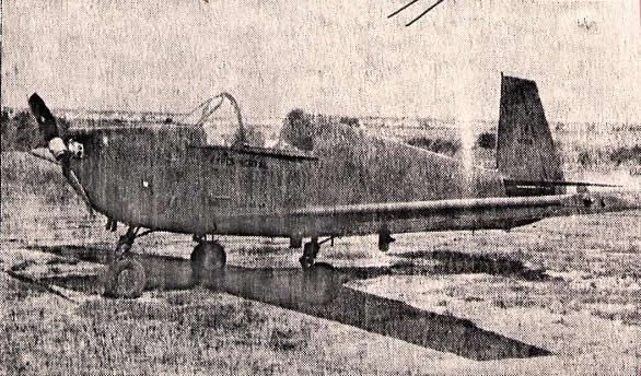
This is a photo of the M-19. Our
apologies for the quality -- it is a copy of a copy of a copy.
According to our files, the one and only M-19 was designated
X499M - Al's personal airplane. It was seriously damaged when Hal
Rochel, who bought the Mooney factory in 1955, tried - for some
unexplained reason - to take off with a stone tied to the tail. Subsequently, it
was purchased by Bob Purcell of Fort Worth, TX. Beyond that,
its fate is unknown.
See also The Mooney M-19, a
First-hand Look by Elroy "Buck" Hilbert