Mooney Mite
by Aubrey Kochman
This article is taken from the December 1949 issue of AIR TRAILS Pictorial.
|
|
| Front page of article | Reduced-scale image of blueprint |
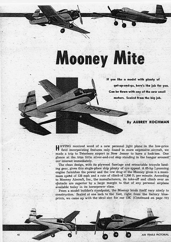
HAVING received word of a new personal light plane in the low-price field incorporating features only found in more expensive aircraft, we made a trip to Teterboro airport in New Jersey to have a look-see. One glance at the trim little silver-and-red ship standing in the hangar aroused our interest immediately.
The clean design, with its plywood fuselage and retractable tricycle landing gear, gives this single-place ship plenty of eye appeal. A Lycoming engine furnishes the power and the low drag of the Mooney gives it a maximum speed of 138 mph and a rate of climb of 1,300 ft. per minute. According to Mooney Aircraft, Inc., the manufacturers, its take-off and climb over an obstacle are superior by a large margin to that of any personal airplane available today in its horsepower class.
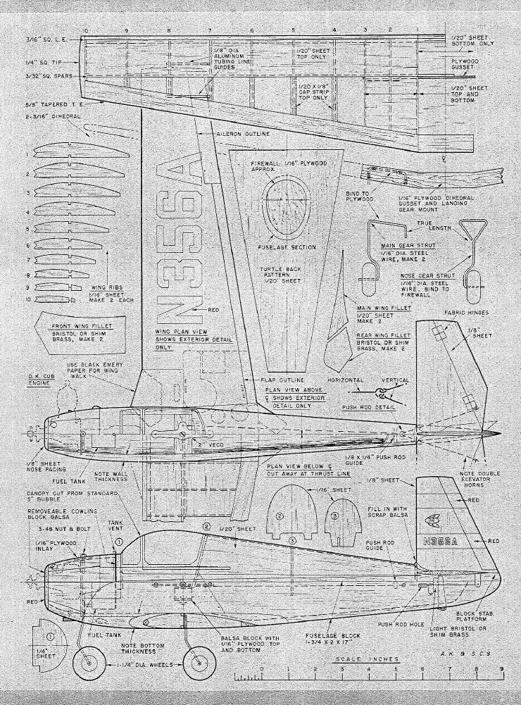
From a model builder's standpoint, Mooney lends itself very nicely to construction. Scaled at one inch to the foot, right from the factory blue-prints, we came up with the ideal size for our OK Cub and found that scale wheels and canopy, usually a bugaboo in a scale model, could be purchased with little trouble at any hobby shop. At first glance the canopy looked like a problem, but after trying a few different sizes, the portion needed was cut from a standard five-inch bubble.
As for construction, select a very soft block of balsa l-¾" x 2" "x 17". This forms the lower half of the fuselage, so trace the side view onto the block and carve to shape. Do the same with the top view. Carve to the outside shape, being careful not to dent or nick the sharp edges at the top corners of the block. When satisfied with the carving operation, proceed to hollow out the inside. Work toward a wall thickness of approximately?" except where the wing joins the fuselage and forward to the nose. At the wing junction leave it about ½" thick, tapering gradually forward to ⅛" at the nose.
Next add the V-shaped block at the tall that forms the stabilizer mount. At this point you will have to install the bellcrank and the rest of the control system. After the top shell is added, you can't get to the innards. The stabilizer is cut from ⅛" sheet of light-weight balsa and sanded to a streamlined airfoil. Cut off the portion that acts as the elevators, round the cut edges of both stabilizer and elevators, and re-assemble with cloth hinges. Two control horns must be used as shown to get tree movement of the elevators.
The push rod is-made in three sections. Make certain that the two short ends that form the "V" are identical in length. Use about .040" wire for these parts and bend a small loop at the end of the push rod just large enough to engage the loops at the ends of the "V" pieces. This connection should be loose enough to allow free movement of all three pieces but not so loose that uneven elevator travel results. Cut a hole on each side of the tail cone so that the push rods pass through to the control horns without rubbing. Install the entire control system and horizontal tail. Add a balsa strip at the point shown to act as a guide to prevent any side movement of the main push rod. This is very important so don't forget to add it at this time.
Cut the three formers to shape and cement them in their proper locations. The turtle deck is cut from 1/20" sheet balsa using the pattern provided. By wetting the outside of the sheet and applying clear dope to the inside, pre-bend the sheet in your hands until the sheet assumes the curve needed. By using plenty of cement and pins and following the above suggestions, you should have little difficulty joining the sheet to the fuselage.
Add the rudder, which is cut from a sheet of ⅛" stock. The space around the rudder where the turtle deck ends should be filled in with scrap balsa. Use 1/20" sheet to fill in the space below the canopy between formers #l and #t2 as shown. The firewall is cut from 1/16" plywood. You will probably have to use the cut-and-try method to arrive at the shape necessary for a good tight fit, and rather than remove a little from the plywood, cut a groove into the balsa where necessary. Do not cement the firewall in place yet.
Cut the fuselage away for the cylinder head and the crankshaft, and hold the engine in place. Mark the mounting hole locations and remove the firewall. Drill the holes, mount the nose wheel strut, using plenty of cement, and bind with thread. Don't forget to drill a ¼" hole through the firewall for the neoprene fuel line. Now cement the unit in place and check, holding the engine in place, for a zero line of thrust. The engine can be bolted in place now or added later, after the model is painted. Cut the head off a 3-48 machine screw and cement and bind it in place vertically to the rear of the firewall as shown. This screw should be just long enough to protrude through the top half of the cowl with the nut in place. This serves to hold the removable cowl top in place.
Now carefully sand the entire fuselage, removing any irregularities where the turtle deck meets the lower half. At this point the fuselage and tail surfaces are given a coat of filler and again sanded smooth.
BUILD the wing in two halves, allowing the leading edge to extend one inch on each half as shown. Sheet the leading edge and capstrip the ribs with 1/20" soft sheet balsa on the top surface only.
Next cut out the dihedral gusset and main landing gear mount from 1/16" plywood. Cut a slot across the bottom of the fuselage so the gusset fits snugly and flush with the bottom of the fuselage. Cement and bind the main gear to the plywood as shown. Now cement the plywood into the fuselage to receive the one-inch extension of the leading edge so that they too will fit flush.
Although the ship has quite a bit of dihedral, note that the center section is straight across the bottom at the trailing edge. To gain this appearance, we used a piece of the tapered trailing edge stock 2" long also recessed into the bottom of the fuselage. Now join the two halves to the fuselage and don't spare the cement. With the wheels in place you should have 4⅛" dihedral from the ground line to the wing tips. When the wing is firmly cemented in place, cut the leading edge away at the dihedral joint until it is flat across the bottom edge. Using 1/20" balsa, sheet the center section both top and bottom as shown. Cover the bottom of the wing with lightweight Silkspan from the third rib out to the tips before applying the balsa sheet.
Now using the patterns, cut out the wing fillets 1/20" sheet for the two main fillets and light Bristol board for the others. A real super job with rivet detail and all can be done if light shim brass is used instead of the Bristol. It can be cut easily with scissors and the rivet detail can be applied by simply pressing a small blunt nail against it from the underside. Just apply enough pressure to form the rivet head but not enough to puncture the brass.
Cover the top of the wing and add some of the scale details such as scoops, inspection plates, hatch slides, etc. Dope the inside of the cockpit and engine cowl, using a bright red fuel-proof dope. Add the instrument panel and the bubble canopy.
As stated previously, the entire ship is painted silver with bright red trim. Tester's silver "Hep" was used. To get a smooth finish with silver without using a spray gun has been a problem until recently. If you have had the same trouble, follow these simple instructions: First brush on a good coat of the silver. When dry, spray on a very thin coat with an ordinary Flit gun. This thin coat is perfect for removing the brush marks and streaks that always seem to spoil a silver paint job. Remember to keep this last coat very thin so that it comes out of the gun in a fine mist.
A simple, way to mask the bubble while spraying is to wet a piece of Silkspan and lay it on the bubble. The soggy Silkspan will stick firmly enough and prevent any spray from sneaking under it. The aileron and flap lines go on with a ruling pen and India ink.
The Mooney emblem on the fin is finished in the following colors: Red "M" with blue outline; white ellipse with red outline; wings blue in front portion with blue outline around white rear portion.
 |
As this model was not intended as a stunt job, an ordinary square tank was used. The model was balanced by the addition of some lead weight in the nose, close to the leading edge of the wing. This slight nose-heavy condition will help eliminate any ballooning tendency in windy weather. |
A full-scale JPEG image (1 inch = 1 inch) of the above "blueprint" is available by request from the Mite Site. It is a large file, 1.7 megs in size.
16 September, 2001