M-18 Rudder Deflection Chart
The following narrative is provided by Tony Terrigno:
A recent discovery was noted by Mal Gross during the refurbishing of his Mite. The mechanic found that the rudder did not travel far enough to the right or left, caused by the built-in stops!
After reviewing the drawings, they determined what angle the travel should be to the left and to the right, noting that the travel angle to the right is greater in order to offset the engine torque.
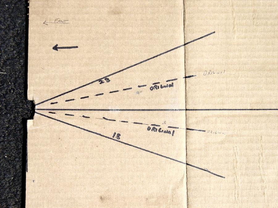
The resultant fix was to grind the stops a little at a time until the proper rudder angel was achieved. The travel angle from the center line of the fuselage is as follows: left travel is 18 degrees; right travel is 23 degrees.
At the last Mite fly-in at Porterville CA, approximately 11 Mites were present. With another person's assistance, I measured numerous aircraft for the rudder travel, and found the following: None came to the angles of the drawing layout used. Some measured just under the 18 and 23 degrees angles of travel, some much less!
The layout which is shown to the left [click to enlarge] should be printed and glued on a piece of cardboard so that you can check your plane's rudder travel. The center line of the fuselage stinger and the distance of each rudder travel must be drawn as shown on this layout.
Stick the cardboard layout between the rudder and stinger. Measure your Mite and if the travel is not as required, within reason, then grind the stops to achieve the necessary rudder travel angle. Better rudder authority will be your reward!!!!!
25 May, 2004