 Mooney Mite Features
|
|
||||||||||||||||||||
| Click on the pictures to enlarge them for viewing.... | ||||||||||||||||||||
| Landing Gear | ||||||||||||||||||||
 |
 |
 |
 |
 |
||||||||||||||||
|
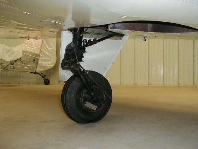
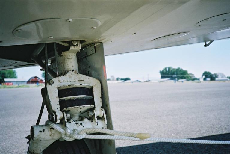
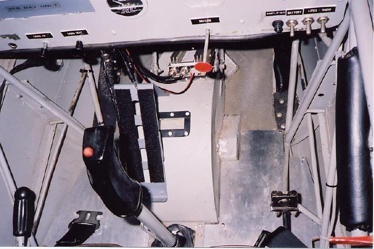
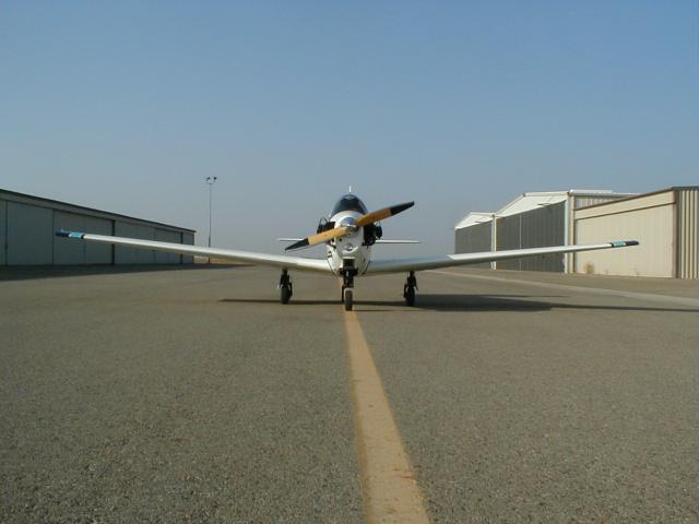
The tricycle landing gear uses rubber donuts for cushioning and a trailing link design. Today's fighter aircraft and business jets now almost all use the trailing link feature. It makes for nice landings and requires very little maintenance. About the only thing that needs attention on the Mite is occasional replacement of the steel bushings for the various linkage. The tires are 400 x 4 tube-type, 4- or 6-ply. The fully retractable landing gear is operated manually by a "Johnson bar" on the right side of the cockpit and uses push-rods to activate the gear. When the lever is locked in the up (vertical) position the gear is down. In some aircraft, it takes a considerable amount of pressure to make the lever click into its detent -- pilots have been known to use the right foot to push it into place! There is no back-up system and none required, since it does not involve hydraulics or electric motors. The steerable nose wheel, when extended, turns with the rudder of course. If you take off in a stiff crosswind and you carry a lot of right rudder, for example, the nose wheel will also be turned to the right. But through some ingenious geometry in the linkage, when you retract the gear, the nose wheel will straighten out so it will fit into the wheel well, even though you still carry a lot of right rudder. |
||||||||||||||||||||
|
|
||||||||||||||||||||
| Propeller | ||||||||||||||||||||
 |
 |
 |
 |
|||||||||||||||||
|
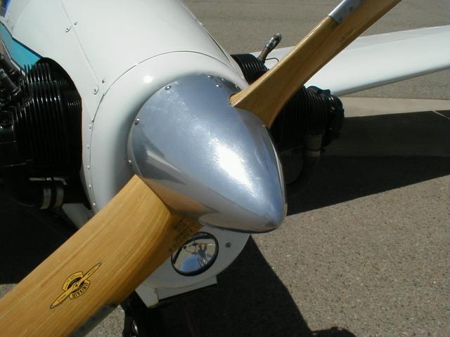
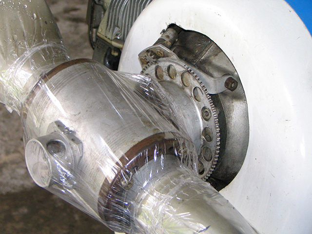
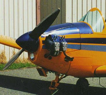
The factory propeller was a Sensenich or Flottorp fixed-pitch wooden propeller, about 60 inches in diameter. An optional "controllable" or variable-pitch (Beech Roby) propeller fitted only the tapered-shaft engines (such as the Continental A65-8). Pitch is adjusted by a small handle, much like the window crank in an old car, projecting from the instrument panel. Most Mites are still equipped with a wooden propeller. It is lighter than a metal prop, and has a further advantage that in case of a prop strike (gear up landing) the engine crankshaft is usually not damaged. The Lycoming 65 was not certified to use a metal prop, but some of the Continental A65 Mites use a metal prop which is probably a little more efficient. Interestingly, the TC (Type Certificate) allows for use of a non-certificated propeller, if the replacement prop meets the same specifications as the certificated type. |
||||||||||||||||||||
|
|
||||||||||||||||||||
| Trim Control | ||||||||||||||||||||
 |
||||||||||||||||||||
|
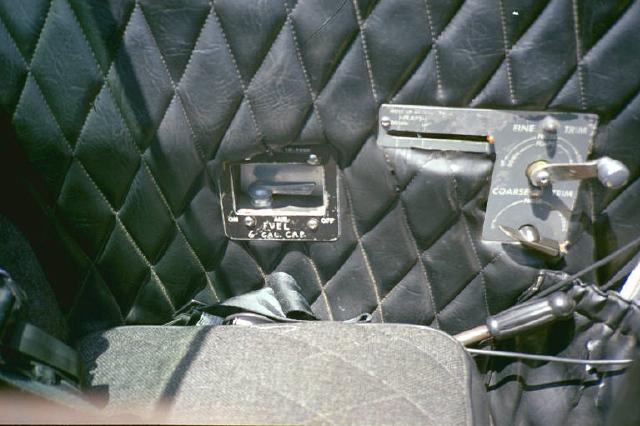
The "Safe-Trim" system, a version of the patented "Simpli-Fly" system, integrates the trim with the flaps. A single crank, operated with the left hand, moves the entire tail assembly (the fin and horizontal stabilizers). As the trim control is gradually cranked to increase the 'up' trim for landing, the flaps are deployed to the maximum of 16.5 degrees down. That may not seem like much, but they have a wide span and thus are very effective. The L model Mite uses cables to operate the trim, while the LA and C models use push-rods. Al Mooney worked at Lockheed for a time and left his signature with the Lockheed Jetstar which also moves the entire tail group to trim. |
||||||||||||||||||||
|
|
||||||||||||||||||||
| Tail Group | ||||||||||||||||||||
 |
 |
 |
||||||||||||||||||
|
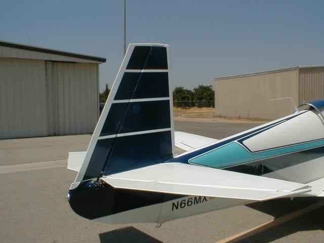
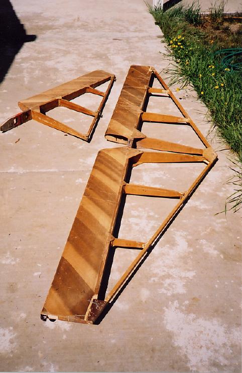
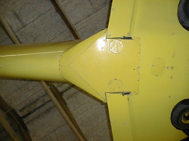
The tail group is attached to a tubular V-frame with three AN3 (3/16 inch) bolts, two of them in tension, and one in shear. This V-frame is then attached to the rear bulkhead with two horizontal bolts at the top, and the bottom of the frame is attached to the trim push-rod, allowing the frame to pivot in a vertical plane. The right-hand photo shows the structure of the vertical fin and horizontal stabilizer. Notice the D-box leading edge, which is also a feature of the main wing. |
||||||||||||||||||||
|
|
||||||||||||||||||||
| Cockpit | ||||||||||||||||||||
 |
 |
 |
 |
 |
 |
|||||||||||||||
|
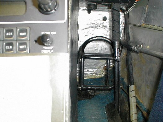
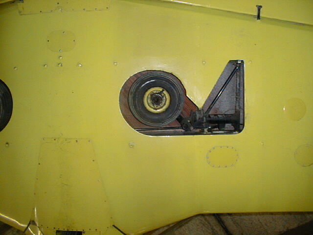
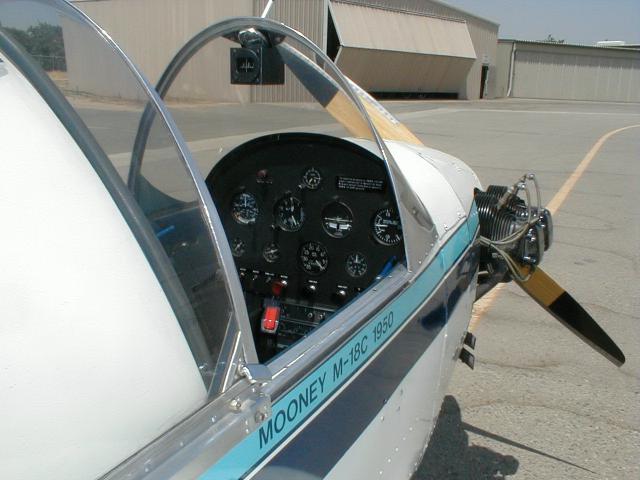
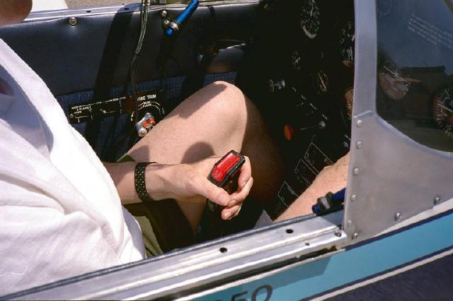
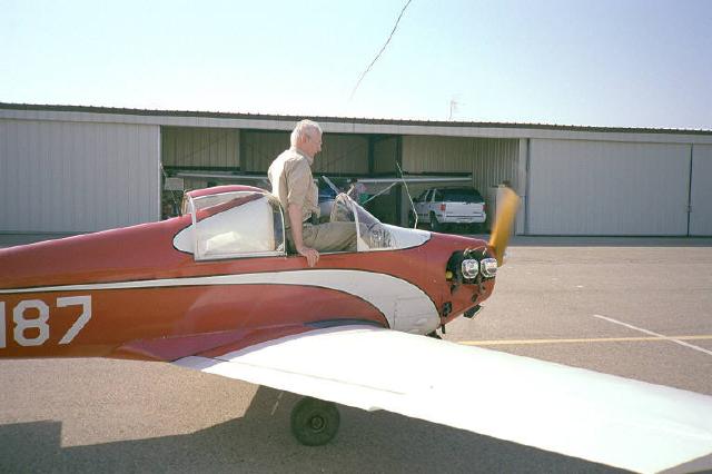
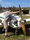
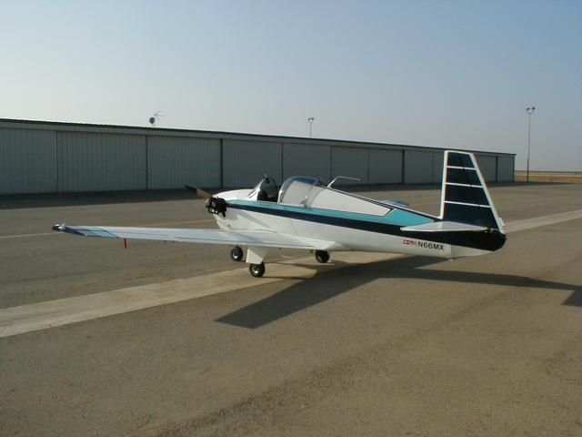
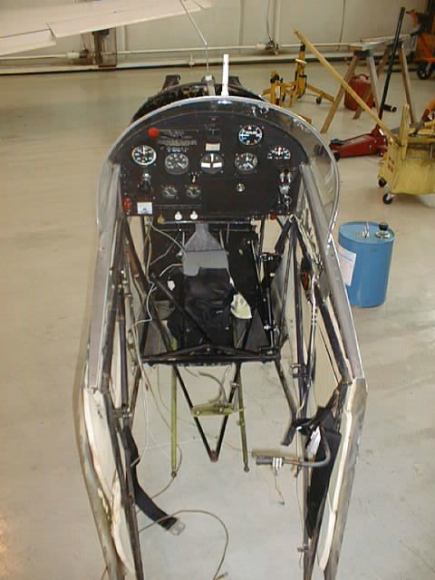
One photo shows how a six-footer fits in the cockpit (with knees raised), while another shows that a 6'-2" pilot can enter without difficulty in the necessarily brief interval between engine start and first application of brakes. The right hand photo shows the small window in the hump of the nose wheel well which allows the pilot to see if the wheel is retracted. The cockpit of the C, L and LA models have the same dimensions: approximately 21.5 inches wide, 30 inches long and 37 inches high. The C-55 model cockpit is the same width, but 5 inches longer and over 2 inches higher than the others. The Mite cockpit is covered with a canopy that slides open to the rear. The Mite can be flown comfortably with the canopy open.
|
||||||||||||||||||||
|
|
||||||||||||||||||||
| Instruments | ||||||||||||||||||||
 |
 |
 |
 |
 |
 |
|||||||||||||||
|
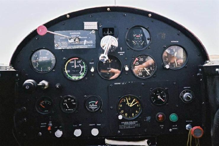
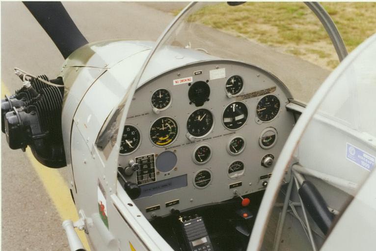
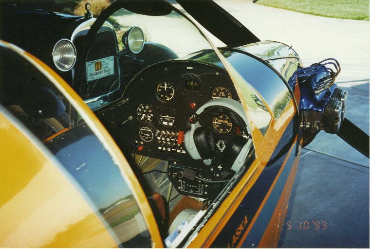
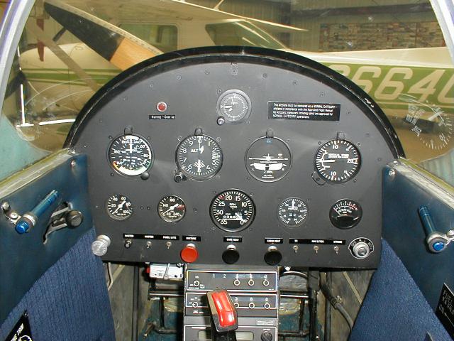
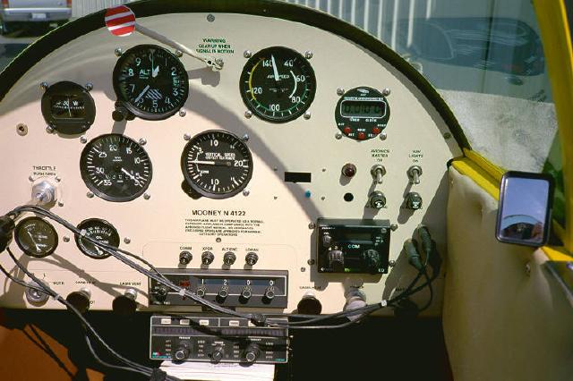
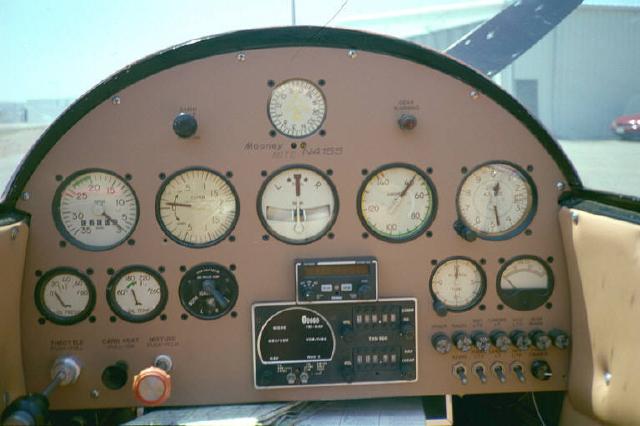
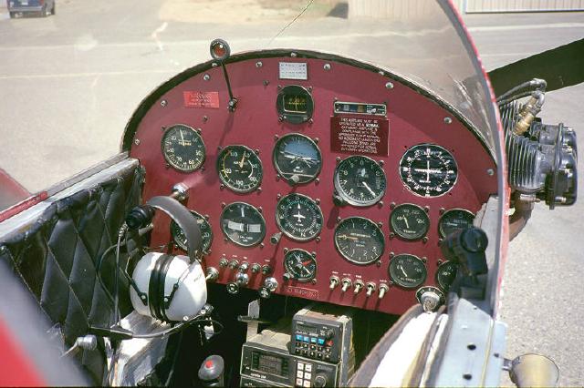
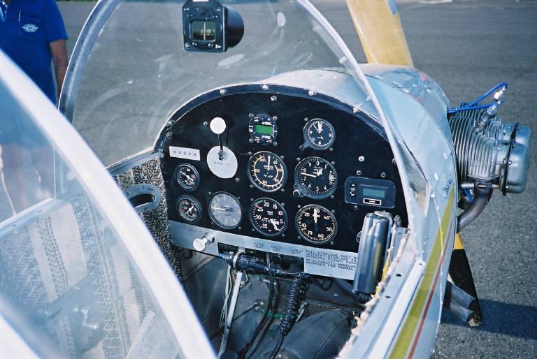
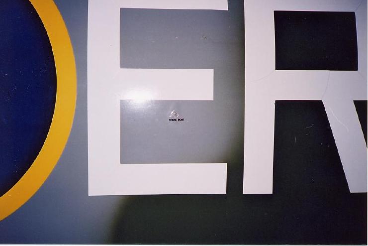
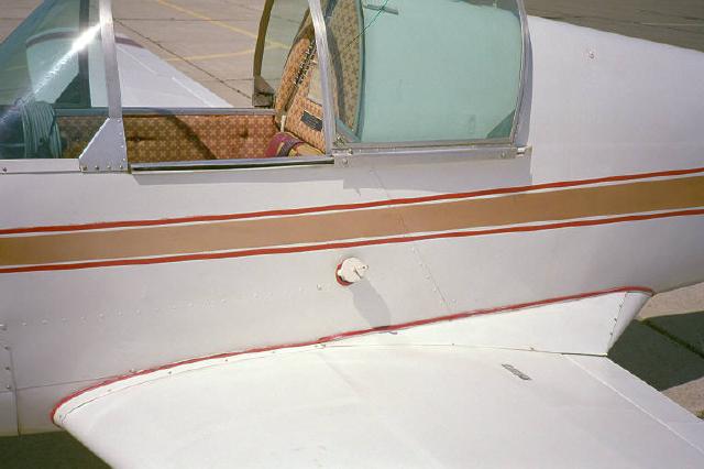
The basic factory-installed instruments, meeting VFR requirements, consist of altimeter, magnetic compass, airspeed indicator, tachometer, oil temperature and pressure gauges, and a fuel gauge. Since the Mites are now more than half century old, most instrument panels have gone through many iterations over the years. Most owners have customized their panels to suit their personal preferences. Some Mites now meet IFR standards. The "Gear-up" warning system is also mechanical because the original Mites had no electrical system. It consists of a Trico vacuum-operated automobile windshield wiper motor which moves a little flagged arm back and forth if the gear is up when the throttle is retarded for landing. (It can be seen in the second photo from the left). Many Mite owners have since retired that method for a more reliable warning system. Newer Mites have a small Plexiglas inspection window in front of the control column (see previous photo), a foolproof way for the pilot to see if the nose wheel (and thus the main gear) is up or down. The last photograph shows the location of the static source which is connected by a tube to the airspeed indicator. This opening is located on the side of the fuselage where it is least affected by airflow during flight. |
||||||||||||||||||||
|
|
||||||||||||||||||||
| Engine | ||||||||||||||||||||
 |
 |
 |
 |
 |
 |
|||||||||||||||
|
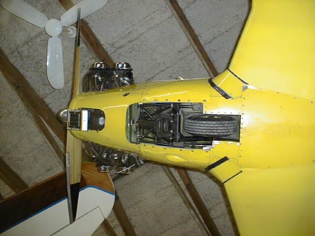
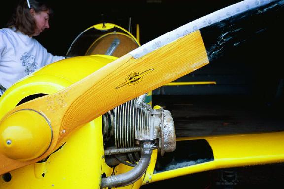
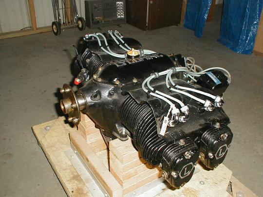
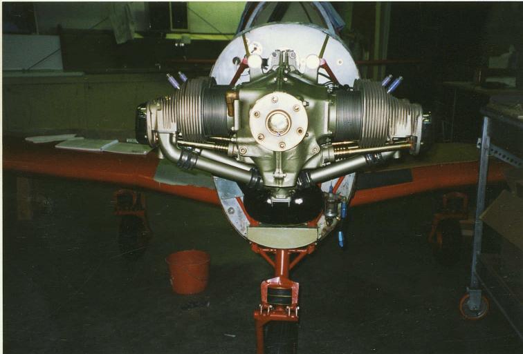
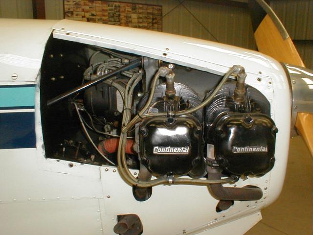
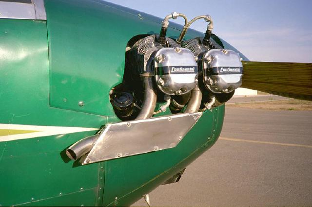
The standard Mite engine is a 65 HP, four-cylinder, air-cooled Lycoming or Continental, burning 80 octane aviation fuel. Except with the later Mite models, which have an electrical system with a starter, the pilot normally starts the engine by flipping the propeller downward with his right hand while standing on the right side the cockpit, the back of his legs against the leading edge of the wing. Notice that the Continental exhaust exits on the right hand side, while the Lycoming is on the left. Although the Lycoming O-145-B2 and the Continental A65 engines both claim 65hp, the Continental has more displacement, and is a more powerful engine. It is also slower turning. But the Lycoming is probably one of the smoothest running four cylinder aircraft engines ever built. |
||||||||||||||||||||
|
|
||||||||||||||||||||
| Fuselage | ||||||||||||||||||||
 |
 |
 |
 |
 |
||||||||||||||||
|
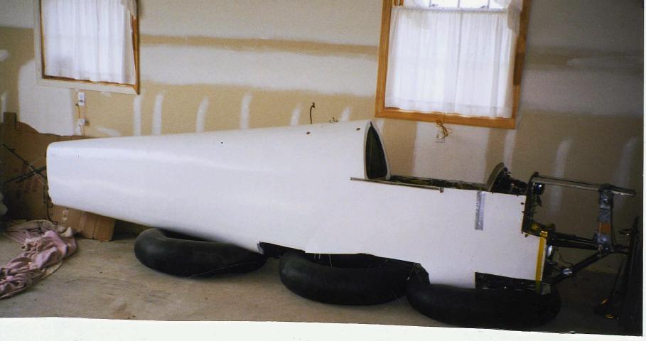
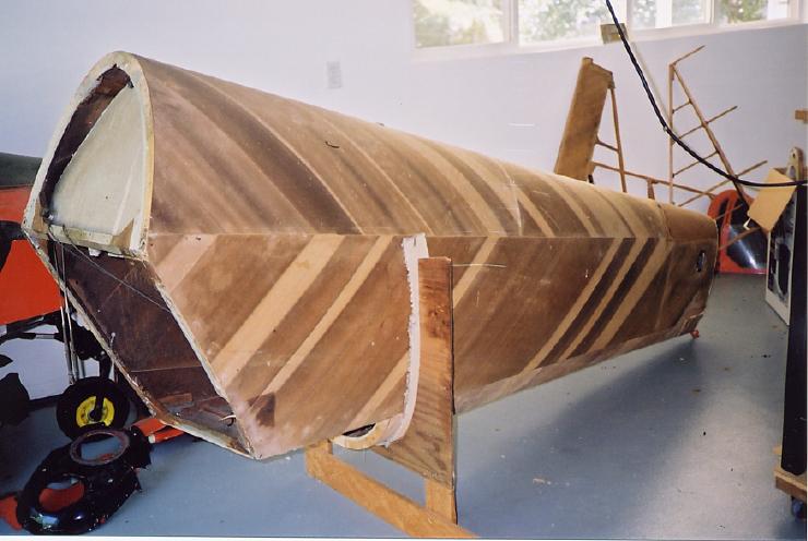
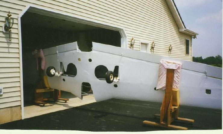
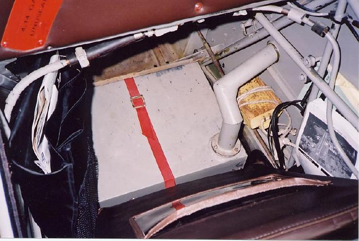
The front portion of the fuselage is tubular steel covered with a skin of aluminum panels from the firewall back as far as the aft cockpit bulkhead. The rest of the fuselage is of semi-monocoque construction, made up of bulkheads and wood stringers (longerons) covered with 45 degree plywood (which is less likely to propagate cracks) over which is a final layer of fabric. Note the metal fuel tank in the end of the fuselage in the right-hand photo. |
||||||||||||||||||||
|
|
||||||||||||||||||||
| Wing | ||||||||||||||||||||
 |
 |
 |
 |
 |
||||||||||||||||
|
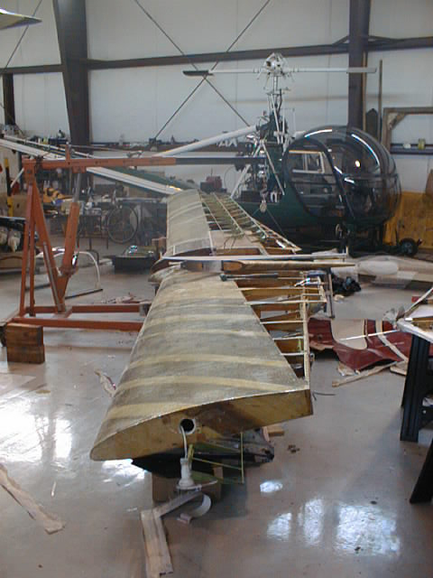
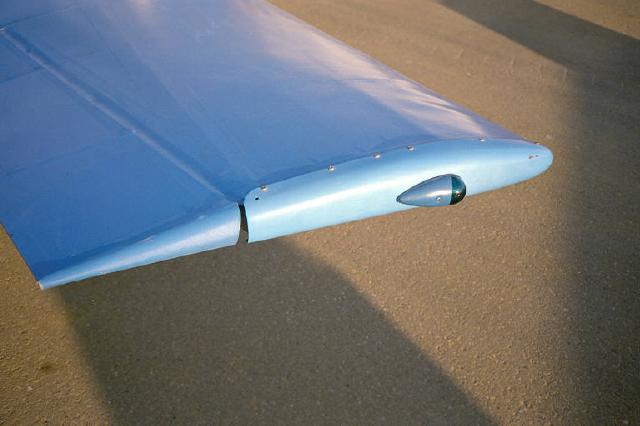
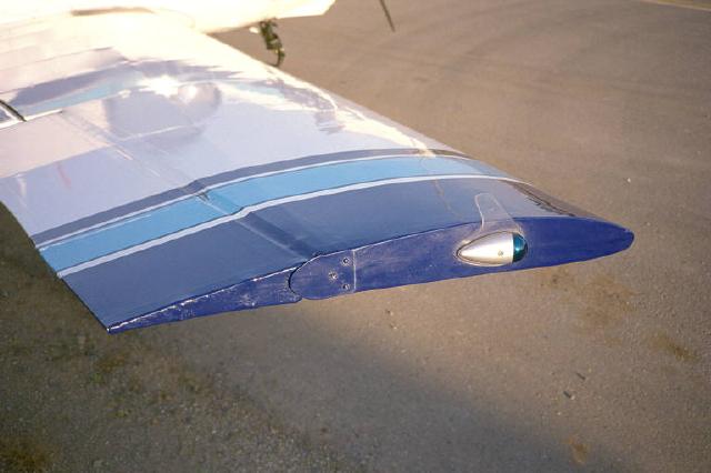
The strongest part of the Mite is the wing. It is a one piece structure, with 15 or more laminations of wood in the center, and fewer laminations as it progresses towards the tip. The fuselage rests on top of the wing, and is held in position with four AN4 (1/4 inch) bolts in shear. The nuts on the bolts only serve to prevent the bolts from falling out. The wing spars are made of spruce because of its superior strength-to-weight ratio. The stringers in the fuselage are also spruce. Most of it comes from Sitka, Alaska, but some also comes from Canada. The plywood covering the fuselage is usually mahogany or birch wood. The favorite birch comes from Finland. The Mite airfoil is a 64215 Laminar for the most part, but the tip section is a NACA 2412 which is not a laminar. Incidentally, the end of the wingtips on earlier models were rounded, while on later Mites they are flat or squared off. |
||||||||||||||||||||
|
|
||||||||||||||||||||
| Fuel Indicator | ||||||||||||||||||||
 |
 |
 |
 |
|||||||||||||||||
|
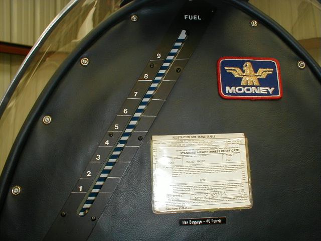
The fuel gauge is a sight tube, like on an old style coffee urn, located behind the pilot's right shoulder. By adding a background of horizontal stripes as shown in the photo, the fuel level is easier to read because the fuel will distort the view of the stripes (above the fuel level, the stripes will look straight). This gauge is difficult to read in flight, so some Mite pilots use the clock to estimate fuel remaining, and some use a small hand-held mirror which works fine. The main fuel tank is located in the fuselage, behind the pilot's seat backrest. It may hold either 9.6 gallons or 11.4 gallons (usable), depending on the model. The Mite has no fuel pump, rather a gravity-feed fuel system, and is therefore non-aerobatic. The flight manual recommends no steep climbs with less than 5.5 gallons of fuel remaining. The second photo from the left shows the optional 6 gallon auxiliary tank located behind the pilot's seat, in the bottom of the fuselage (actually in the centre section of the wing). Note the filler neck. The right hand photos show the aux. tank filler cap in the side of the fuselage, and the handle of the wobble pump to the left of the seat. Operated with the left hand, it pumps the fuel up into the main tank giving a combined total usable fuel capacity of 15.6 gallons. |
||||||||||||||||||||
|
|
||||||||||||||||||||
| Our thanks to Ben Favrholdt for providing most of the above information. | ||||||||||||||||||||
|
|
||||||||||||||||||||
- Maintenance Page: Tips and Techniques
- Specifications
- M-18C Flight Manual (Adobe .pdf format)
- M-18L Flight Manual (Adobe .pdf format)
- To see Mite photos, go to the Owners page